Ease in modification of logic, reduced size, means of remote communications and advances in the technology have made PLC programmable logic control panel & totally made by customized logic, machinery operation logic & controlling with computerized.
PLC panel is a special steel box that contains electrical components required to run a factory machine or process. PLC stands for Programmable Logic Controller, an industrial hardened computer usually found inside factory control panels.
It is an industrial computer control system that continuously monitors the status of input devices and makes decisions based upon a custom program to control the status of output devices.
Invention and early development
PLC originated in the late 1960s in the automotive industry in the US and were designed to replace relay logic systems. Before, control logic for manufacturing was mainly composed of relays, cam timers, drum sequencers, and dedicated closed-loop controllers.
The hard-wired nature made it difficult for design engineers to alter the automation process. Changes would require rewiring and careful updating of the documentation. If even one wire were out of place, or one relay failed, the whole system would become faulty. Often technicians would spend hours troubleshooting by examining the schematics and comparing them to existing wiring. When general-purpose computers became available, they were soon applied to control logic in industrial processes. These early computers were unreliable and required specialist programmers and strict control of working conditions, such as temperature, cleanliness, and power quality.
Many early PLCs were not capable of graphical representation of the logic, and so it was instead represented as a series of logic expressions in some kind of Boolean format, similar to Boolean algebra. As programming terminals evolved, it became more common for ladder logic to be used, because it was a familiar format used for electro-mechanical control panels. Newer formats, such as state logic and Function Block (which is similar to the way logic is depicted when using digital integrated logic circuits) exist, but they are still not as popular as ladder logic. A primary reason for this is that PLCs solve the logic in a predictable and repeating sequence, and ladder logic allows the person writing the logic to see any issues with the timing of the logic sequence more easily than would be possible in other formats.
A PLC is an industrial microprocessor-based controller with programmable memory used to store program instructions and various functions. It consists of:
PLCs require programming device which is used to develop and later download the created program into the memory of the controller.
Compact PLC with 8 inputs and 4 outputsModular PLC with EtherNet/IP module, discrete and analog I/O, with some slots being empty
There are two types of mechanical design for PLC systems. A single box, or a brick is a small programmable controller that fits all units and interfaces into one compact casing, although, typically, additional expansion modules for inputs and outputs are available. Second design type – a modular PLC – has a chassis (also called a rack) that provides space for modules with different functions, such as power supply, processor, selection of I/O modules and communication interfaces – which all can be customized for the particular application.
Discrete (digital) signals can only take on or off value (1 or 0, true or false). Examples of devices providing a discrete signal include limit switches, photoelectric sensors and encoders. Discrete signals are sent using either voltage or current, where specific extreme ranges are designated as on and off. For example, a controller might use 24 V DC input with values above 22 V DC representing on, values below 2 V DC representing off, and intermediate values undefined.
Analog signals can use voltage or current that is proportional to the size of the monitored variable and can take any value within their scale. Pressure, temperature, flow, and weight are often represented by analog signals. These are typically interpreted as integer values with various ranges of accuracy depending on the device and the number of bits available to store the data. For example, an analog 0 to 10 V or 4-20 mA current loop input would be converted into an integer value of 0 to 32,767. The PLC will take this value and transpose it into the desired units of the process so the operator or program can read it. Proper integration will also include filter times to reduce noise as well as high and low limits to report faults. Current inputs are less sensitive to electrical noise (e.g. from welders or electric motor starts) than voltage inputs. Distance from the device and the controller is also a concern as the maximum traveling distance of a good quality 0-10 V signal is very short compared to the 4-20 mA signal. The 4-20 mA signal can also report if the wire is disconnected along the path as a < 4 mA signal would indicate an error.
Some special processes need to work permanently with minimum unwanted downtime. Therefore, it is necessary to design a system that is fault-tolerant and capable of handling the process with faulty modules. In such cases to increase the system availability in the event of hardware component failure, redundant CPU or I/O modules with the same functionality can be added to hardware configuration for preventing total or partial process shutdown due to hardware failure. Other redundancy scenarios could be related to safety-critical processes, for example, large hydraulic presses could require that both PLCs turn on output before the press can come down in case one output does not turn off properly.
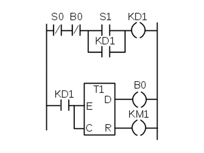
Programmable logic controllers are intended to be used by engineers without a programming background. For this reason, a graphical programming language called Ladder Diagram (LD, LAD) was first developed. It resembles the schematic diagram of a system built with electromechanical relays and was adopted by many manufacturers and later standardized in the IEC 61131-3 control systems programming standard. As of 2015, it is still widely used, thanks to its simplicity.
PLC programs are typically written in a programming device, which can take the form of a desktop console, special software on a personal computer, or a handheld programming device. Then, the program is downloaded to the PLC directly or over a network. It is stored either in non-volatile flash memory or battery-backed-up RAM. In some programmable controllers, the program is transferred from a personal computer to the PLC through a programming board that writes the program into a removable chip, such as EPROM.
Manufacturers develop programming software for their controllers. In addition to being able to program PLCs in multiple languages, they provide common features like hardware diagnostics and maintenance, software debugging, and offline simulation.
PLC simulation is a feature often found in PLC programming software. It allows for testing and debugging early in a project's development.
Incorrectly programmed PLC can result in lost productivity and dangerous conditions. Testing the project in simulation improves its quality, increases the level of safety associated with equipment and can save costly downtime during the installation and commissioning of automated control applications since many scenarios can be tried and tested before the system is activated.
PLC system in a rack, left-to-right: power supply unit (PSU), CPU, interface module (IM) and communication processor (CP) Control panel with PLC (grey elements in the center). The unit consists of separate elements, from left to right; power supply, controller, relay units for input and output
The main difference from most other computing devices is that PLCs are intended-for and therefore tolerant-of more severe conditions (such as dust, moisture, heat, cold), while offering extensive input/output (I/O) to connect the PLC to sensors and actuators. PLC input can include simple digital elements such as limit switches, analog variables from process sensors (such as temperature and pressure), and more complex data such as that from positioning or machine vision systems. PLC output can include elements such as indicator lamps, sirens, electric motors, pneumatic or hydraulic cylinders, magnetic relays, solenoids, or analog outputs. The input/output arrangements may be built into a simple PLC, or the PLC may have external I/O modules attached to a fieldbus or computer network that plugs into the PLC.
The most basic function of a programmable controller is to emulate the functions of electromechanical relays. Discrete inputs are given a unique address, and a PLC instruction can test if the input state is on or off. Just as a series of relay contacts perform a logical AND function, not allowing current to pass unless all the contacts are closed, so a series of "examine if on" instructions will energize its output storage bit if all the input bits are on. Similarly, a parallel set of instructions will perform a logical OR. In an electromechanical relay wiring diagram, a group of contacts controlling one coil is called a "rung" of a "ladder diagram ", and this concept is also used to describe PLC logic. Some models of PLC limit the number of series and parallel instructions in one "rung" of logic. The output of each rung sets or clears a storage bit, which may be associated with a physical output address or which may be an "internal coil" with no physical connection. Such internal coils can be used, for example, as a common element in multiple separate rungs. Unlike physical relays, there is usually no limit to the number of times an input, output or internal coil can be referenced in a PLC program.
PLCs use built-in ports, such as USB, Ethernet, RS-232, RS-485, or RS-422 to communicate with external devices (sensors, actuators) and systems (programming software, SCADA, HMI). Communication is carried over various industrial network protocols, like Modbus, or EtherNet/IP. Many of these protocols are vendor specific.
PLCs used in larger I/O systems may have peer-to-peer (P2P) communication between processors. This allows separate parts of a complex process to have individual control while allowing the subsystems to co-ordinate over the communication link. These communication links are also often used for HMI devices such as keypads or PC-type workstations.
Formerly, some manufacturers offered dedicated communication modules as an add-on function where the processor had no network connection built-in.
PLCs may need to interact with people for the purpose of configuration, alarm reporting, or everyday control. A human-machine interface (HMI) is employed for this purpose. HMIs are also referred to as man-machine interfaces (MMIs) and graphical user interfaces (GUIs). A simple system may use buttons and lights to interact with the user. Text displays are available as well as graphical touch screens. More complex systems use programming and monitoring software installed on a computer, with the PLC connected via a communication interface.
A PLC works in a program scan cycle, where it executes its program repeatedly. The simplest scan cycle consists of 3 steps :
The program follows the sequence of instructions. It typically takes a time span of tens of milliseconds for the processor to evaluate all the instructions and update the status of all outputs. If the system contains remote I/O—for example, an external rack with I/O modules—then that introduces additional uncertainty in the response time of the PLC system.
As PLCs became more advanced, methods were developed to change the sequence of ladder execution, and subroutines were implemented. This enhanced programming could be used to save scan time for high-speed processes; for example, parts of the program used only for setting up the machine could be segregated from those parts required to operate at higher speed. Newer PLCs now have the option to run the logic program synchronously with the IO scanning. This means that IO is updated in the background and the logic reads and writes values as required during the logic scanning.
In his book from 1998, E. A. Parr pointed out that even though most programmable controllers require physical keys and passwords, the lack of strict access control and version control systems, as well as an easy-to-understand programming language make it likely that unauthorized changes to programs will happen and remain unnoticed.
Prior to the discovery of the Stuxnet computer worm in June 2010, the security of PLCs received little attention. Modern programmable controllers generally contain a real-time operating systems, which can be vulnerable to exploits in a similar way as desktop operating systems, like Microsoft Windows. PLCs can also be attacked by gaining control of a computer they communicate with. Since 2011, these concerns have grown as networking is becoming more commonplace in the PLC environment connecting the previously separate plant floor networks and office networks.
Safety PLCs can be either a standalone model or a safety-rated hardware and functionality added to existing controller architectures (Allen-Bradley Guardlogix, Siemens F-series etc.). These differ from conventional PLC types by being suitable for safety-critical applications for which PLCs have traditionally been supplemented with hard-wired safety relays and areas of the memory dedicated to the safety instructions. The standard of safety level is the SIL.
A safety PLC might be used to control access to a robot cell with trapped-key access, or to manage the shutdown response to an emergency stop on a conveyor production line. Such PLCs typically have a restricted regular instruction set augmented with safety-specific instructions designed to interface with emergency stops, light screens, and so forth.
The flexibility that such systems offer has resulted in rapid growth of demand for these controllers.
PLC installed in a control panelControl center with a PLC for a RTO
PLCs are well adapted to a range of automation tasks. These are typically industrial processes in manufacturing where the cost of developing and maintaining the automation system is high relative to the total cost of the automation, and where changes to the system would be expected during its operational life. PLCs contain input and output devices compatible with industrial pilot devices and controls; little electrical design is required, and the design problem centers on expressing the desired sequence of operations. PLC applications are typically highly customized systems, so the cost of a packaged PLC is low compared to the cost of a specific custom-built controller design. On the other hand, in the case of mass-produced goods, customized control systems are economical. This is due to the lower cost of the components, which can be optimally chosen instead of a "generic" solution, and where the non-recurring engineering charges are spread over thousands or millions of units.
A microcontroller-based design would be appropriate where hundreds or thousands of units will be produced and so the development cost (design of power supplies, input/output hardware, and necessary testing and certification) can be spread over many sales, and where the end-user would not need to alter the control. Automotive applications are an example; millions of units are built each year, and very few end-users alter the programming of these controllers. However, some specialty vehicles such as transit buses economically use PLCs instead of custom-designed controls, because the volumes are low and the development cost would be uneconomical.
Very complex process control, such as those used in the chemical industry, may require algorithms and performance beyond the capability of even high-performance PLCs. Very high-speed or precision controls may also require customized solutions; for example, aircraft flight controls. Single-board computers using semi-customized or fully proprietary hardware may be chosen for very demanding control applications where the high development and maintenance cost can be supported. "Soft PLCs" running on desktop-type computers can interface with industrial I/O hardware while executing programs within a version of commercial operating systems adapted for process control needs.
The rising popularity of single board computers has also had an influence on the development of PLCs. Traditional PLCs are generally closed platforms, but some newer PLCs (e.g. groov EPIC from Opto 22, ctrlX from Bosch Rexroth, PFC200 from Wago, PLCnext from Phoenix Contact, and Revolution Pi from Kunbus) provide the features of traditional PLCs on an open platform.
PLCs may include logic for single-variable feedback analog control loop, a PID controller. A PID loop could be used to control the temperature of a manufacturing process, for example. Historically PLCs were usually configured with only a few analog control loops; where processes required hundreds or thousands of loops, a distributed control system (DCS) would instead be used. As PLCs have become more powerful, the boundary between DCS and PLC applications has been blurred.
In more recent years, small products called programmable logic relays (PLRs) or smart relays, have become more common and accepted. These are similar to PLCs and are used in light industries where only a few points of I/O are needed, and low cost is desired. These small devices are typically made in a common physical size and shape by several manufacturers and branded by the makers of larger PLCs to fill out their low-end product range. Most of these have 8 to 12 discrete inputs, 4 to 8 discrete outputs, and up to 2 analog inputs. Most such devices include a tiny postage-stamp-sized LCD screen for viewing simplified ladder logic (only a very small portion of the program being visible at a given time) and status of I/O points, and typically these screens are accompanied by a 4-way rocker push-button plus four more separate push-buttons, similar to the key buttons on a VCR remote control, and used to navigate and edit the logic. Most have a small plug for connecting via RS-232 or RS-485 to a personal computer so that programmers can use simple applications in general-purpose OS like MS Windows, macOS or Linux, that have user-friendly (G)UIs, for programming instead of being forced to use the tiny LCD and push-button set for this purpose. Unlike regular PLCs that are usually modular and greatly expandable, the PLRs are usually not modular or expandable, but their price can be two orders of magnitude less than a PLC, and they still offer robust design and deterministic execution of the logic.